Switch an LED on and off with the Raspberry Pi and Python.
ⓘ Cet article peut avoir été partiellement ou totalement traduit à l'aide d'outils automatiques. Nous nous excusons des erreurs que cela pourrait engendrer.
This tutorial is the first in a series dedicated to using the Raspberry Pi's GPIO ports to control electronic components.
As you probably know, the Raspberry Pi has ports called GPIO (General Purpose Input Output) which allow you to control a number of electronic components.
In this tutorial, we will see how to use these GPIO ports to control an LED with the Raspberry Pi.
The necessary equipment
To follow this tutorial, you will need the following materials:
This tutorial can be followed completely without needing to solder any component.
In addition, you will need to have Raspbian installed on your SD card, and have a way to control your Raspberry Pi, either directly via keyboard / mouse / screen, or via SSH.
The basics around GPIOs
GPIO ports are physical ports generally in the form of square metal pins that allow an electrical signal to be transmitted.

A GPIO port transmits a relatively binary signal (no current or current). In the case of the Raspberry Pi, the GPIO ports work at 3.3 V and around 20 mA.
GPIO ports are therefore a simple way to communicate or control physical elements.
The most recent models of the Raspberry Pi have 40 GPIO connectors, which are divided into different categories with specific uses.
- Power +: Continuous power supply
- GND: Ground = Return to earth
- I2C: Synchronous serial protocol
- SPI: Other synchronous serial protocol
- UART: Asynchronous protocol + serial to parallel communication conversion.
- GPIO: General port which can optionally be transformed into I2C or SPI.
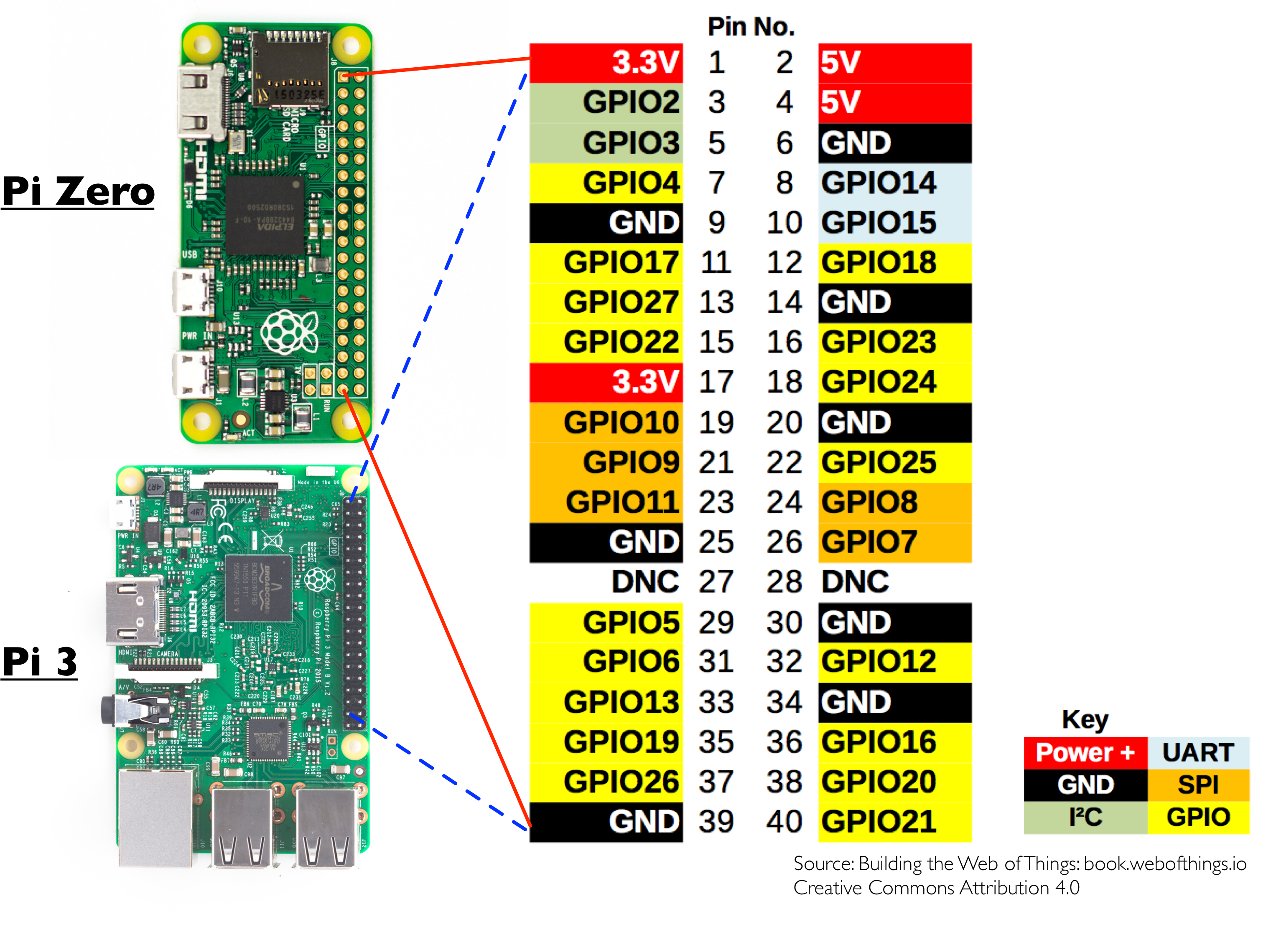
The GPIO ports are numbered 1 to 40, starting from the top left when you hold the Raspberry pi GPIO ports to the right. This is the so-called "Board" numbering mode. Another numbering mode exists, which is based on processor addressing, called "BCM" mode.
In the context of this tutorial we will only use the GPIO and GND type ports and the "Board" numbering.
Connect the LED to the Raspberry Pi
To make our connection we will use the following components: an LED, a resistor, a bread-board and the Raspberry.
The first step of our tutorial will be to design the circuit connecting the LED to the Raspberry Pi. Don't worry, it's very simple and we aren't going to have to do complicated diagrams!
How to choose the resistance?
The first thing to know is that an LED must always use a resistor. This is because LEDs have what is called a "threshold voltage". To put it simply, a little too much current and the LED burns out immediately, so the resistor is a protection.
We will therefore have to choose which resistance to use. For this, there is a mathematical formula to calculate the size of the resistor to use.
Rmin = (Ualim - Uled) / ImaxUnless you have some good leftovers from your physics class, I'm guessing it doesn't get you too far. Small explanation:
- Rmin: Minimum resistance to use, expressed in ohms (Ω)
- Ualim: Power supply voltage, expressed in volts (V)
- Uled: LED threshold voltage, expressed in volts (V)
- Imax: The maximum intensity of the LED, expressed in amperes (A)
As we said, our GPIOs provide 3.3 V and 20 mA. The LED has a maximum intensity of 20 mA (20 mA = 0.020 A) and a threshold voltage of 1.5 and 1.9 V.
The formula is therefore the following:
Rmin = (3.3 - 1.5) / 0.020We therefore obtain a minimum resistance of 90 Ω, which we will round to 100 Ω. We will take some room by choosing a 270 Ω resistor instead (or 330 Ω, normalized values), thus protecting us from a possible current peak on the GPIO.
To find the value of a resistance, two possibilities:
- This is noted on the strip of paper that holds the LEDs together.
- You need to read the color rings on the resistor to calculate its value. You will find tutorials and sites online to help you. (100 Ω = brown-black-brown, 270 Ω = red-purple-brown and 330 Ω = orange-orange-brown)
Connect the LED to the GPIOs of the Raspberry Pi
Now that we know which resistor to use, we just have to connect everything to the Raspberry Pi.
For that, take two Dupont male / female cables, we will choose a red cable for the power supply, and a black cable for the return to earth (it is a convention).
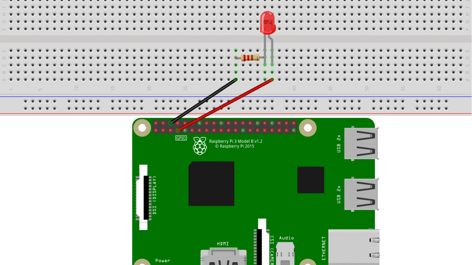
Connect the red cable to GPIO port 7, and the black cable to GPIO 6.
Connect the two cables to your bread-board separated by a few rows. Connect the red cable to the anode of your LED (the elongated or long leg), one leg of the resistor to the cathode (the other leg of the LED, the short leg therefore), and the other leg of the resistor to the black cable.
Tip: Having trouble remembering which leg is the anode and which is the cathode? Simple mnemonic, the Elongated Anode Feeds!
It's not very clear? Don't panic, "a little drawing is better than a long speech!"
If you want to make sure everything is working fine, a little simple test is possible. Unplug the red cable from GPIO # 7 and plug it into # 1. This provides 3.3 V permanently, if your wiring is correct, the LED will be on :)!
Write the program to control the LED with the Raspberry
Now that our circuit is ready, we just have to write the program to control the GPIO ports to turn the LED on and off.
For this, we are going to use the Python programming language. In this tutorial we will stay very basic, and we will just give an example of a program explaining how to use it and how it works.
So this is not a Python course. However, if you want to we recently published an Introductory Python course that will teach you how to use Python to write your own programs for your projects!
So create a folder /home/pi/electronic and a file led.py in that folder, and write the following code there:
Note that the texts behind # are comments used to explain what the code does, but have no influence on the program. You don't have to copy it, except for the first two lines.
#!/usr/bin/env python3
#-- coding: utf-8 --

import RPi.GPIO as GPIO #Importe la bibliothèque pour contrôler les GPIOs

GPIO.setmode(GPIO.BOARD) #Définit le mode de numérotation (Board)
GPIO.setwarnings(False) #On désactive les messages d'alerte

LED = 7 #Définit le numéro du port GPIO qui alimente la led

GPIO.setup(LED, GPIO.OUT) #Active le contrôle du GPIO

state = GPIO.input(LED) #Lit l'état actuel du GPIO, vrai si allumé, faux si éteint

if state : #Si GPIO allumé
    GPIO.output(LED, GPIO.LOW) #On l’éteint
else : #Sinon
    GPIO.output(LED, GPIO.HIGH) #On l'allume
This done, we will make the program executable. To do this, simply run the following command:
chmod +x /home/pi/electronic/led.py
All you have to do is run the script by calling it like this:
/home/pi/electronic/led.py
Each time you run the script, the LED will turn on if it is off, and turn off if it is on.
And there you have it, you now know the basics of turning an LED on and off with the Raspberry Pi. All you have to do is adapt the code to suit your needs. For that, do not hesitate to consult our course on Python!
All you have to do is move on to the next tutorial in this series, read an RFID card with the Raspberry Pi!