How to plug in and use a GSM SIM800L module with the Raspberry Pi (without battery).
ⓘ Cet article peut avoir été partiellement ou totalement traduit à l'aide d'outils automatiques. Nous nous excusons des erreurs que cela pourrait engendrer.
The SIM800L is a GSM/GPRS modem that is widely used in electronics due to its very low price and wide availability. It’s an affordable way to send SMS with a Raspberry Pi or Arduino, connect in 3G or implement a GPS.
However, it is almost impossible to find satisfactory explanations about its use and especially about its connection.
So in this tutorial we’ll see how to plug in and power a SIM800L from a Raspberry (note that it also works for an Arduino), without external power or battery!
The hardware needed to connect your SIM800L to your Raspberry.
We will go into the details and explanations later in this tutorial, but be aware that to link a SIM800L to a Raspberry a little hardware is needed. So you’ll need:
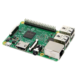
- From a SIM800L module.
- A soldering iron to assemble your SIM800L if it is not already.
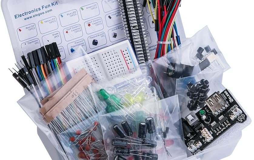
- A breadboard, a capacitor 5 V, 100µF or more, a 1N4007 diode, Dupont cables. You could buy each item alone, but you should actually buy dozens of capacitors and diodes just to pay off the shipping costs. So I think the easiest thing is to take an electronics kit like this that contains everything we just mentioned.
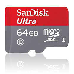
Of course, you’ll also need a Raspberry with raspbian installed and a SIM card with a subscription. Note that the SIM card must be in micro sim format. If yours is a smaller size (nano), you will need an adapter.
Now let’s move on to explanations and practice.
No time or desire to read the explanations? Go directly to the “In Practice…” part.
Theory, how to use a SIM800L with a Raspberry Pi?
The SIM800L is a modem. It is the one who registers with your operator’s network, etc. Overall it behaves like a phone that you could control directly from your Raspberry.
In order to control the SIM800L, from the Raspberry, you will have to provide power to the first and physically and softwareally connect both using a TTL port, more often called a port or serial interface.
From there you can control the SIM800L by sending hayes commands to the series port – in fact more often REFERRED to as AT commands – which are commands specific to the functions of a modem. For example, sending an SMS, entering a PIN, checking the status of the network, and much more!
In theory, to use a SIM800L with the Raspberry Pi you must therefore do like this:
- Connect the SIM800L VDD to a GPIO providing power on the Raspberry.
- Connect the SIM800L GND to a GND GPIO on the Raspberry.
- Link the SIM800L TXD to the Raspberry RXD.
- Link the Raspberry’s RXD to the SIM800L TXD.
- Send and receive data with AT commands on the serial port.
Only here, all this is the theory, but you will see that in practice things are a little more complicated …
The reality is, why is it difficult to plug in a SIM800L?
If the theory sounds simple, in reality you will find quite a few tutorials on the internet explaining how to use the SIM800L with a Raspberry. Worse, you will essentially find incorrect tutorials that, at best, will make your installation completely unstable, at worst, will damage your SIM800L.
But then, how is it that there are not more quality resources available for such a well-known module? Because SIM800L is particularly difficult to feed and sensitive.
A module designed for phones and batteries.
Originally the SIM800L was designed to be used in phones by manufacturers. Its use in consumer electronics is much more recent and has not been considered at all by the manufacturer.
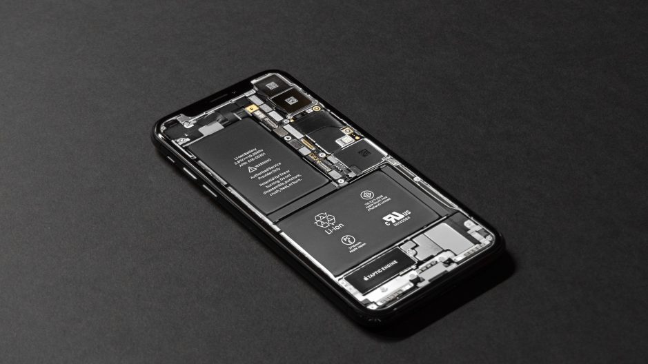
As a result of its use within phones, the module is designed to be powered with lithium-ion batteries, which offer voltages of about 3.6 to 3.7 volts. This feature will pose a first problem, because in digital electronics we usually use 3.3 volts or 5 volts, but not 3.6 volts.
An energy-hungry module.
The second problem is that the SIM800L performs radio operations that require large, very punctual current peaks. Typically the operations involved are recording on the operator’s network, sending messages, etc. If during these phases the module does not get the necessary current its behavior becomes completely unpredictable, ranging from the error message to the restart through the loss of network.
Unfortunately, it turns out that the supplies in general and the GPIO ports of the Raspberry Pi in particular have a hard time responding to these kinds of peaks in consumption.
In fact, the amount of energy consumed is so large and over such a short period of time that using power cables that are too long and thin can be enough to crash the module! This is typically the case if you plug several Dupont cables in series.
Rest assured, we’ll explain how to solve these two problems!
In practice, how do you power a SIM800L directly from a Raspberry?
So we saw that we have two problems to power a SIM800L from a Raspberry: inconsistent voltage and peaks in power consumption.
First, we’re going to tackle the tension problem.
Reduce the voltage provided by the Raspberry Pi.
If we read the datasheet, that is, the technical sheet, of the SIM800L, we see that the manufacturer indicates a power voltage of 3.4 and 4.4 volts, with an optimal voltage of 4 volts.
The Raspberry Pi can provide two voltages, 3.3 and 5 volts. So we should increase our blood pressure a little bit or decrease it.
Let us eliminate the first possibility which is too complicated to implement and look at the second. We are therefore looking for a reliable, simple and very inexpensive way to reduce a voltage of at least 0.6 volts, without decreasing the intensity of the current (ampers). Luckily, it turns out that there is an electronic component that does just that, and that in addition this component is so widespread that absolutely all electronics know it: the diode.
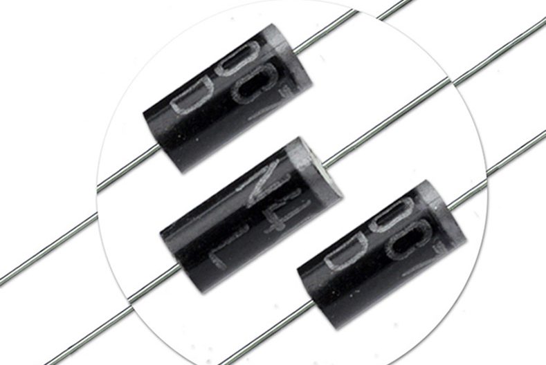
Diodes are mainly known to let the current pass in one direction. But one of their characteristics is also to cause a voltage drop, which is estimated for silicon diodes at 0.7 volts.
So we just have to insert a silicon diode, we will take a 1N4007, between the GPIO 5 volts of our Pi and the PIN VDD (food) of our SIM800L. And that’s it, we have a voltage of 4.3 volts, just what we need.
Provide a power source that can respond to peak consumption.
Now that we have solved our voltage problem, remains our problem of peak consumption. This time we would need a component that would allow us to “store power” and provide it very quickly when the SIM800L needs it. Again luckily, it exists and it’s called a capacitor!

Capacitors are used in many cases, but one of the most well-known uses is power stabilization. They load when there is too much power and discharge when there is a shortage.
So we’re going to insert an electrolytic capacitor (we’ll take at least a 100µF 5 V, if we have more in µF or volts no problems) in parallel to the VDD and GND pin of our SIM800L.
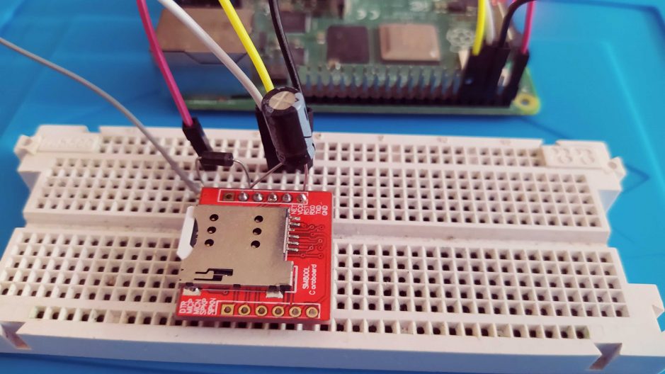
The complete assembly.
Now that we’ve solved our problems, let’s see what our full edit looks like before testing everything by texting.
To keep all our components in place and connect them together we will use a breadboard and Dupont cables.
So here is the final connection diagram, the red thread goes to the VDD, the black to the GND.

A few comments about editing:
- Make the Raspberry connections off and not plugged in, plug it in only after you’ve checked everything and make sure your edit is good.
- Be careful to connect the capacitor as close as possible to the SIM800L VDD and GND pin, ideally as on the diagram.
- The capacitor is a polarized component, it must be plugged in a precise direction, anode on the VDD, cathode on the GND. The cathode is marked by a white stripe on the side.
- Like the capacitor, the diode is a polarized component, again the cathode is marked by a white band.
Once the assembly is complete you will be able to insert the SIM card in the location provided on the SIM800L.
Pay close attention to the meaning, it is absolutely not intuitive. You have to tuck the card side contacts against the circuit board, the corner cut skewed towards the aperture (it exceeds a little). If you enter the card upside down you will have a typical error SIM not inserted using the module.
Once the assembly is complete, turn on your Raspberry Pi, we’ll be able to test by sending an SMS!
Send your first SMS from the Raspberry with a SIM800L.
To finish this tutorial, we will send a first SMS to check that everything works. We will not go further on the use of the SIM800L, but know that it offers many other features. For further use, see the AT command guide for the SIM800.
To start, you’ll have to follow our tutorial to activate the raspberry Pi series port. Once you have finished activating the series port we will be able to connect to the SIM800L via the series port.
To do this, open a connection to /dev/serial0 with minicom using the command line below:
sudo minicom -b 115000 -o -D /dev/serial0Type in the command AT (often the first line doesn’t show up when you type, it’s normal) and then go back to the line to validate. You should have a reply message OK.
Now we will check that the SIM card is unlocked (the PIN is entered). To do this type the command AT+CPIN?. If the card is unlocked you should have an answer:
+CPIN: READY
OK
If you have an answer like the one below it is because you have to enter the PIN of your card.
+CPIN: SIM PIN
OK
To do this use the command AT+CPIN=0000 replacing 0000 by your own PIN. You should then have an answer in the form:
AT+CPIN=0000
OK
+CPIN: READY
SMS Ready
Call Ready
It’s okay, you’re connected to your operator’s network. All we have to do is send a text message. To do this use the commands AT+CMGF=1 to activate the text mode (it allows us to write the SMS in a format understandable to a human), then AT+CMGS="+33612345678" replacing +33612345678 by the number to which you want to send the SMS.
A character > will appear, type your sms and then once you’re done, do Ctrl+Z.
In the end you should have something of the following form:
AT+CMGF=1
OK
AT+CMGS="+33612345678"
> Mon premier SMS avec un SIM800L
+CMGS: 29

OK
And lo and behold, you sent your first SMS with a Raspberry Pi and a SIM800L!
As you can see the daily use directly with AT commands is not necessarily very practical, but rest assured, software exists to simplify your life, and we will talk about it very soon in another tutorial!


Hi,
All R-Pi datasheet say that the GPIO output voltage is 3.3V, I never found it as 5V?
Please clarify.
If you take a look to the Raspberry Pi GPIO documentation (https://www.raspberrypi.org/documentation/usage/gpio/) you can see that GPIO 2 & 4 output voltage is 5V.
Hello,
Nice aticle, here a young startup from Paris.
Just a little question, you mean 100uF non?
Best regards,
Alberto
Hello, yes of course ! Sorry it’s a translation bug !
For info, if your in Paris, the website is also available in french (original language).